
Project
Our main project “Advanced Thermal runaway Detection and Delay System forEV Batteries Using Multi-Sensor Integration.”
On the first day of the course, the professor discussed the idea of working on a project. I proposed an idea focused on preventing explosions in EV batteries due to thermal runaway. I shared the concept with Sai Vijay Sankar Bheemana, and he was excited to collaborate. We decided to divide the work: he would handle the machine learning aspect, while I would focus on designing the system.
Proposal
This is a our proposal which we have submitted and it was approved by professor.
Milestone 2
We did a presentation in the class about the project and dicussed about the prototype implementation.
Project Documentation
Integrated Thermal Runaway Prevention System
for Electric Vehicle Batteries Using Multi-Sensor
Fusion and PCM Activation
Intoduction
With the increasing adoption of electric vehicles (EVs), ensuring battery safety has become a critical engineering challenge. One of the most dangerous failure modes in lithium-ion batteries[1] is thermal runaway—a rapid, uncontrollable rise in temperature that can lead to fires, explosions, or the release of toxic gases. To address this issue, this project proposes a real-time thermal runaway detection[2] and prevention system designed to actively monitor and respond to early warning signs within EV battery packs[3].
The system employs a combination of thermal and gas sensors to detect anomalies. An Adafruit AMG8833 infrared thermal camera continuously monitors the battery’s surface temperature[2], producing a thermal map that reveals localized heating. Simultaneously, an MQ-135 gas sensor[4] detects the presence of hazardous gases that may be released during early-stage battery degradation. These sensor readings are processed by an ESP32 S3 microcontroller, which serves as the system’s central processing unit.
Upon detecting abnormal thermal or gas conditions, the ESP32 S3 initiates two key safety actions. First, it activates a NEMA17 stepper motor, controlled by an Adafruit DRV8833 driver, to push a block of Phase Change Material (PCM)[5] upward toward the battery. This PCM absorbs excess heat and physically separates the battery from potential ignition sources. Second, a warning message is sent to the driver or owner through the device connected to the microcontroller via Bluetooth. Third, the system uses an Adafruit N-channel power MOSFET to immediately break the electrical connection to the battery, halting further energy discharge and reducing the risk of escalation.
The entire setup is enclosed with the battery securely mounted at the edges and the PCM positioned below. The ESP32 S3 and sensors are powered by a 5V battery, while a separate 12V supply drives the motor and driver. This modular and responsive design offers a low-cost yet effective safety mechanism that can be integrated into electric vehicles, enhancing both user safety and system reliability.
System Design and Architecture
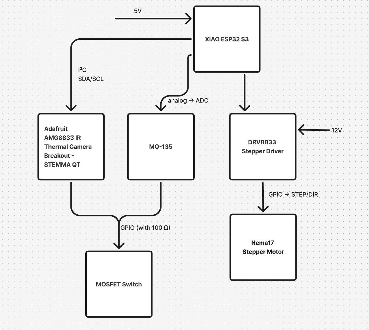
The proposed system is designed to detect and mitigate thermal runaway events in lithium-ion batteries used in electric vehicles. It integrates thermal sensing, gas detection, mechanical intervention, electrical disconnection, and remote warning notifications into a compact, responsive, and coordinated architecture.
At the core of the system is the ESP32-S3 microcontroller, which serves as the central unit for processing sensor data and controlling actuation mechanisms. The ESP32-S3 receives real-time input from two key sensors: the Adafruit AMG8833 IR thermal camera, which provides an 8x8 grid of temperature readings to detect heat buildup across the battery surface, and the MQ-135 gas sensor, which monitors the presence of harmful gases such as ammonia, benzene, or carbon monoxide that are typically released during early battery degradation. These sensors continuously feed data to the ESP32-S3, enabling real-time evaluation of the thermal and chemical environment inside the battery.
When the sensor readings exceed predefined thresholds, indicating the onset of thermal runaway, the system initiates a two-fold response. First, it activates a NEMA17 stepper motor, controlled by an Adafruit DRV8833 motor driver, to push a block of Phase Change Material (PCM) vertically toward the battery. This PCM is strategically placed in the bottom section of the system and acts as a thermal buffer, absorbing large amounts of heat as it transitions from solid to liquid. The use of PCM is based on thermodynamic principles, specifically the ideal gas law (PV = nRT), to reduce the rate of temperature and pressure rise in the system.
Simultaneously, the ESP32-S3 triggers an Adafruit N-channel power MOSFET to immediately disconnect the battery from the load or charging circuit. This rapid electrical isolation prevents further energy flow and minimizes the risk of fire or explosion. In addition to local safety measures, the system incorporates Bluetooth Low Energy (BLE) communication to keep the driver or vehicle owner informed in real-time. Once a thermal runaway warning condition is detected, the ESP32-S3 sends a BLE message to a mobile device or driver’s dashboard that is paired with the microcontroller. This message includes the current status of the battery (e.g., temperature, gas sensor readings) and alerts the driver about the detected anomaly. The driver can receive immediate notifications, which may prompt them to take further action, such as stopping the vehicle or initiating an emergency shutdown.
The system is powered by a 5V battery source for the ESP32-S3 and sensors, while the stepper motor and its driver are powered by a separate 12V power supply, allowing efficient operation of both logic-level and high-power components. This architecture provides a fast, reliable, and modular approach to EV battery safety. By combining passive thermal control, active mechanical response, real-time sensing, and remote BLE notifications, the system aims to detect and mitigate thermal runaway events before they escalate into dangerous situations.
Component Description
1. ESP32-S3 Microcontroller
The ESP32-S3 microcontroller is the central processing unit of the system. It is responsible for reading sensor data, making decisions based on predefined thresholds, and triggering appropriate actions. The ESP32-S3’s Bluetooth Low Energy (BLE) capabilities allow it to send real-time warning notifications to a connected mobile device or dashboard, alerting the driver or vehicle owner of potential thermal runaway conditions. Its processing power also enables efficient handling of sensor inputs and motor control in a low-latency manner.
2. Adafruit AMG8833 IR Thermal Camera
The Adafruit AMG8833 is an 8x8 thermal infrared camera that measures temperature at multiple points on the battery’s surface. This thermal sensor provides critical data that can identify abnormal heat buildup across the battery pack. It works by detecting infrared radiation emitted by objects (in this case, the battery), allowing for precise spatial thermal measurements that can pinpoint localized overheating issues. The ESP32-S3 processes these measurements to detect the onset of thermal runaway.
3. MQ-135 Gas Sensor
The MQ-135 gas sensor is employed to detect the presence of harmful gases that may be released during battery degradation or thermal runaway events, such as ammonia, benzene, carbon monoxide, and other volatile compounds. These gases are often emitted as a result of overheating or internal faults in lithium-ion batteries. The MQ-135 provides real-time data on gas concentration, and if the sensor detects dangerous levels, it signals the microcontroller to take preventive actions.
4. NEMA17 Stepper Motor
The NEMA17 stepper motor is used to control the movement of the Phase Change Material (PCM) block in the system. The stepper motor is connected to an Adafruit DRV8833 motor driver, which provides the necessary control signals to accurately move the motor in small, discrete steps. The motor pushes the PCM upwards when a thermal runaway warning is triggered, allowing the PCM to absorb heat and mitigate temperature rise inside the system.
5. Adafruit DRV8833 Motor Driver
The DRV8833 is a dual H-bridge motor driver that controls the NEMA17 stepper motor. It provides the necessary current and voltage to drive the motor with precision and efficiency. This motor driver ensures smooth operation of the motor, allowing it to push the PCM material in response to detected thermal anomalies.
6. Adafruit N-channel Power MOSFET
The Adafruit N-channel MOSFET is responsible for disconnecting the battery from its load or charging circuit when the system detects thermal runaway conditions. By rapidly switching off the power, the MOSFET prevents further energy flow into the battery, which reduces the risk of fire, explosion, or other catastrophic failures. The MOSFET is controlled by the ESP32-S3 and provides a quick response to safety-critical events.
7. Phase Change Material (PCM) - Paraffin Wax
Paraffin wax has been selected as the Phase Change Material (PCM) due to its excellent thermal management properties and phase-change characteristics. Paraffin wax typically changes its phase at around 60°C, but in a laboratory setting, the wax can be specially formulated to withstand higher temperatures, ranging from 100°C to 120°C. This higher temperature tolerance allows the PCM to absorb a larger amount of heat before it melts, making it highly effective for managing the heat generated in thermal runaway conditions. The PCM absorbs excess thermal energy by transitioning from solid to liquid, thus delaying the rapid rise in temperature that typically accompanies thermal runaway. This phase-change mechanism is key in preventing the battery from reaching critical temperatures that could lead to catastrophic failure.
8. Power Supply
The system utilizes two power supplies: a 5V battery that powers the ESP32-S3 microcontroller, sensor modules, and BLE communication, and a 12V power supply dedicated to driving the stepper motor and its driver. The 12V power supply ensures that the motor has enough torque and precision to move the PCM material effectively. This dual-power setup allows for optimized operation of both low- and high-power components.
9. Bluetooth Low Energy (BLE) Communication
The ESP32-S3 microcontroller uses BLE communication to wirelessly send real-time warnings and updates to the driver or owner of the vehicle. Once a thermal runaway event is detected, the ESP32-S3 sends a message to the connected device, such as a smartphone or car dashboard, providing the user with up-to-date information on the battery’s status, including temperature readings, gas concentrations, and system alerts. This feature ensures the driver is always informed of potential safety issues.
Machine Learning
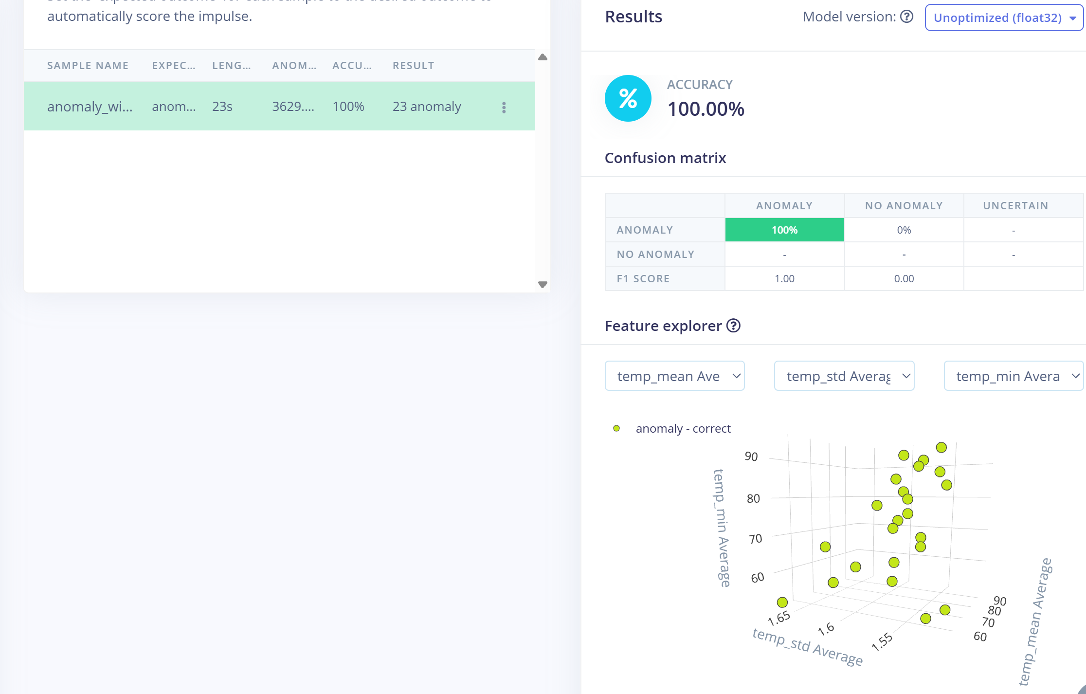
The machine learning model for anomaly detection was developed using Edge Impulse. Sensor data collected from the thermal camera and gas sensor under normal operating conditions was used to train the model. The processing block utilized was a Flatten block, and the learning block was set to Anomaly Detection using Gaussian Mixture Models (GMM). After training, the model was tested within Edge Impulse using a custom, auto-generated anomaly dataset. Since this test dataset contained only anomalous data, the resulting test accuracy was 100%. Following the successful evaluation, the trained model was deployed by exporting it as a .zip library and importing it into the Arduino IDE environment as a new custom library.
PCB Layout
The hardware layout is designed to optimize the accessibility and functionality of all connected modules. A 1×3 male pin header is placed on the top side of the PCB to connect the MOSFET switch for controlling the battery circuit. A 2×8 male header is also provided on the top side for interfacing the stepper motor driver (DRV8833), ensuring stable power and signal connections. For the gas sensing module, a 1×4 female header with a 2.54 mm pitch is positioned on the bottom side of the board, allowing compact placement of the MQ-135 sensor. Additionally, two JST connectors are located on the top side: a 1×4 header with a 1.00 mm pitch for the AMG8833 thermal camera, and a 1×4 header with a 2.00 mm pitch for the stepper motor. This arrangement balances space constraints while maintaining ease of access for wiring and component integration.
Code Structure
The heart of this sketch is a simple sense-decide-act cycle driven by your thermal camera, gas sensor, and Edge Impulse anomaly model. After pin and constant definitions at the top, setup() brings up three things in order: the AMG8833 thermal sensor (halting on failure), the BLE radio (so a phone or dashboard can connect), and the Edge Impulse model in flash. It also configures the MOSFET gate and the four DRV8833 motor-driver lines as outputs, turning the LED on by default.
In each half-second iteration of loop(), the code first samples the 8×8 temperature array and the MQ-135 gas reading, then computes a very simple “trend” by comparing to the prior values. The single critical check is “has the maximum temperature just crossed 50 °C and no alarm is active?” At that moment the sketch performs three prioritized actions—(1) immediately switch off the MOSFET/LED, (2) send one BLE notification “Warning: thermal runaway detected,” and (3) rotate the stepper motor the exact number of steps needed to deploy the PCM block about 20 mm. A latch flag prevents any of those steps from repeating or the LED from turning back on once an anomaly is confirmed.
All other code (periodic status prints, manual Serial commands, trend math) simply supports that core safety response. By grouping initialization into setup() and leaving only the sensing, decision, and three-step actuation in loop(), the program stays focused on the one job that matters most: detect thermal runaway early and react—LED off, BLE alert, PCM deployed—before anything else.
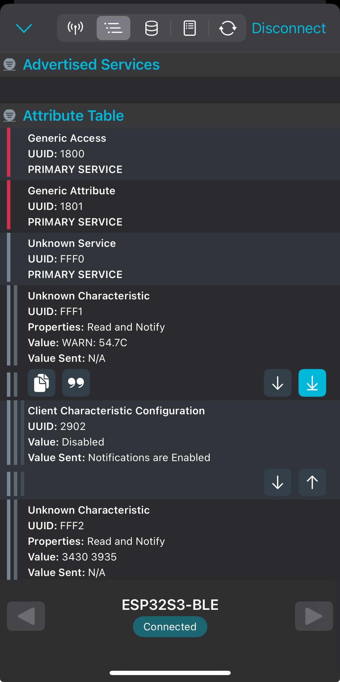
This diagram illustrates the BLE link between the ESP32-S3 and a smartphone. Once the onboard Edge Impulse model flags an anomaly (thermal runaway), the ESP32-S3 instantly transmits a warning message over Bluetooth Low Energy. The phone, running a compatible BLE client, receives that alert in real time, enabling the user to take immediate action.
3D – Printing
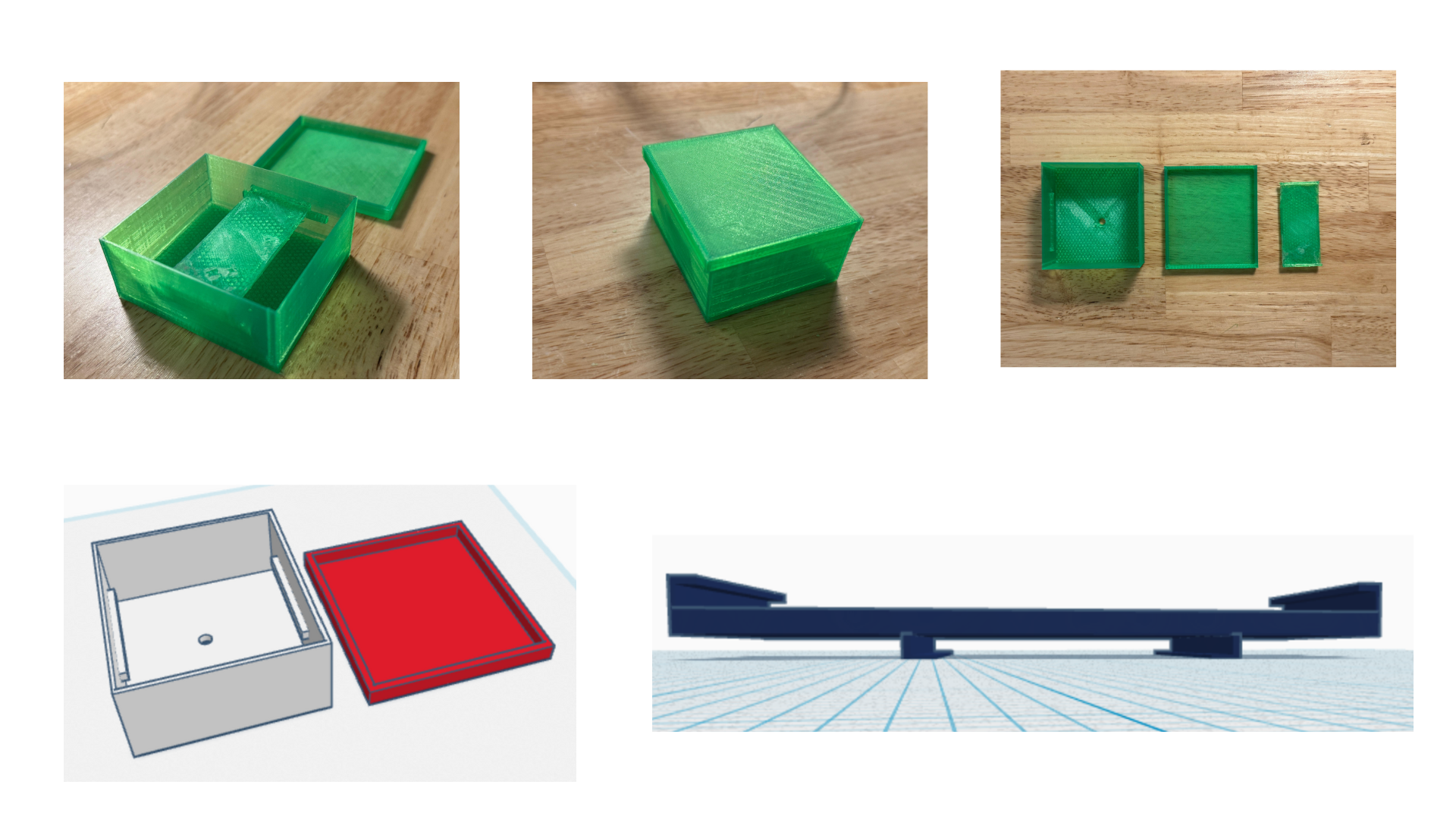
The thermal camera is secured in a two-part 3D-printed holder that integrates directly with the PCB. The top half of the holder slides seamlessly through an opening in the PCB and locks into the bottom half, which features a form-fitting cavity for the AMG8833 module. Once assembled, the camera is oriented downward through the PCB, ensuring an unobstructed view of the battery surface for accurate thermal sensing. This slide-in design allows easy removal for maintenance or replacement, while maintaining a rigid, vibration-resistant mount during operation.
The main enclosure is a custom-designed box with two opposing side rails that clip onto the edges of the PCB, holding it firmly in the center of the chamber. These rails not only secure the electronics but also ensure consistent spacing between the sensors and the battery surface. On the underside of the box, directly beneath the thermal camera’s field of view, a precision-cut hole accommodates the motor’s lead-screw shaft. This opening allows the stepper-driven PCM carriage to extend through the floor of the enclosure and press against the bottom of the battery when deployed. The combined holder and enclosure design delivers a compact, modular assembly that aligns all components for reliable sensing, actuation, and thermal management.
Work Distribution
-
Linto Thomas
Hardware & 3D Design: PCB layout in KiCad, pin-to-component wiring, and 3D-printable holder/enclosure. -
Sai Vijay Sankar Bheemana
ML & Firmware: Sensor data collection, Edge Impulse anomaly model, and ESP32 Arduino code.
References
[1] T. M. Bandhauer, S. Garimella, and T. F. Fuller, “A Critical Review of Thermal Issues in Lithium-Ion Batteries,” J. Electrochem. Soc., vol. 158, no. 3, p. R1, Jan. 2011, doi: 10.1149/1.3515880.
[2] D. Meng, J. Weng, and J. Wang, “Experimental Investigation on Thermal Runaway of Lithium-Ion Batteries under Low Pressure and Low Temperature,” Batteries, vol. 10, no. 7, Art. no. 7, Jul. 2024, doi: 10.3390/batteries10070243.
[3] Q. Wang, P. Ping, X. Zhao, G. Chu, J. Sun, and C. Chen, “Thermal runaway caused fire and explosion of lithium ion battery,” J. Power Sources, vol. 208, pp. 210–224, Jun. 2012, doi: 10.1016/j.jpowsour.2012.02.038.
[4] X.-X. Wang, Q.-T. Li, X.-Y. Zhou, Y.-M. Hu, and X. Guo, “Monitoring thermal runaway of lithium-ion batteries by means of gas sensors,” Sens. Actuators B Chem., vol. 411, p. 135703, Jul. 2024, doi: 10.1016/j.snb.2024.135703.
[5] S. K. Maknikar and A. M. Pawar, “Application of phase change material (PCM) in battery thermal management system (BTMS): A critical review,” Mater. Today Proc., Aug. 2023, doi: 10.1016/j.matpr.2023.08.329.